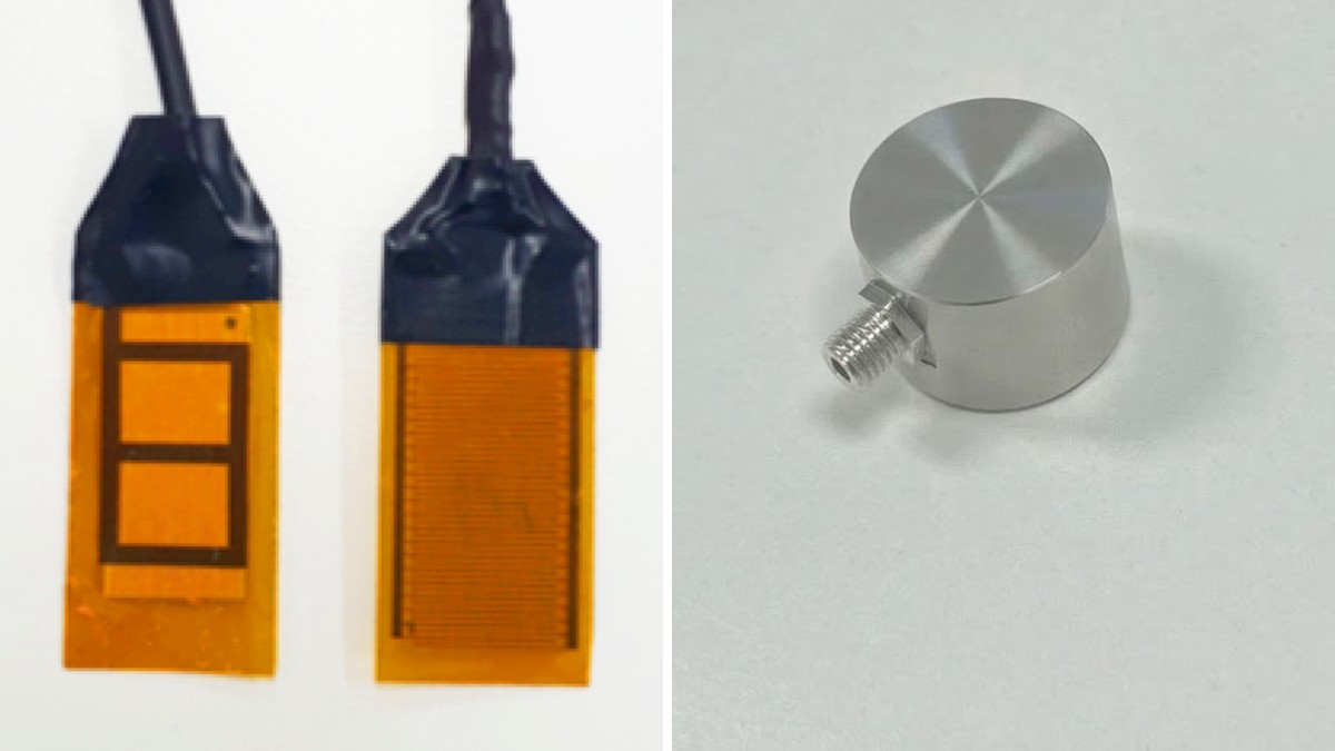
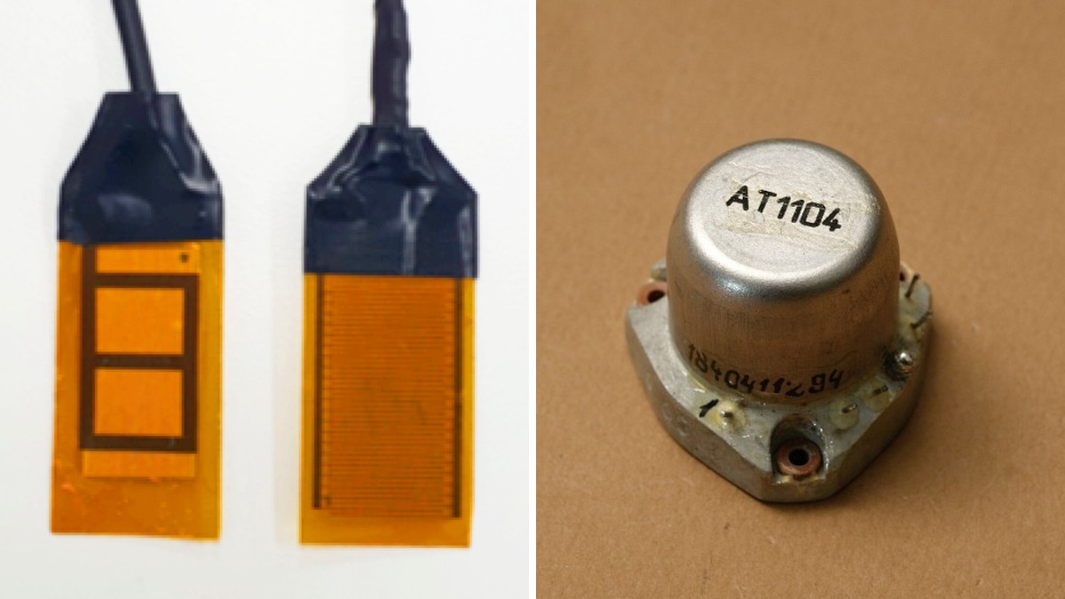
- Choose the frequency band and form of an AE sensor according to the phenomenon you want to detect.
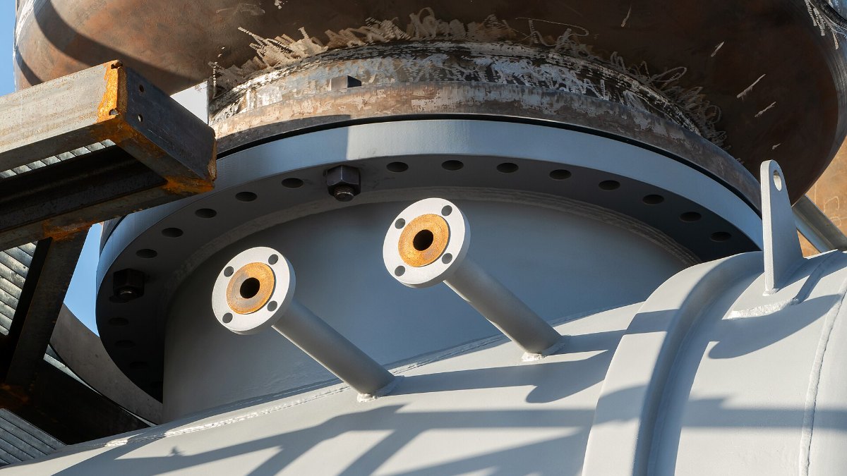
- On curved pipes, the contact between sensor and surface determines signal quality.
- Also review the installation environment (temperature, explosion protection), sensor spacing and data processing.
The right AE sensor specification depends on what you want to detect, the shape of the mounting surface and the operating environment. This article lists, in order, what to check when selecting an AE sensor.
1. Frequency band: decide what you want to detect first
Most AE sensors fall into two groups: resonant sensors, most sensitive at a specific frequency, and broadband sensors, which respond evenly over a wide range. Resonant sensors are highly sensitive and widely used for field monitoring; broadband sensors are mainly used in research and testing where the waveform itself must be analyzed.
| Band | Typical use | Characteristics |
|---|---|---|
| Low frequency (tens of kHz) | Pipeline leaks, tank floor corrosion, large structures | Travels far, good for monitoring wide areas, but more affected by machine noise |
| Mid frequency (about 100–300 kHz) | Cracks in pressure vessels and pipes, rotating machinery defects and general equipment monitoring | Good balance of sensitivity and noise avoidance; the most widely used |
| High frequency (several hundred kHz and above) | Micro-cracks, small components, micro-defects in processes | Robust to noise but strongly attenuated, so the monitoring range is small |
AE equipment manufacturers, for example, also recommend low-frequency sensors for large structures, highly attenuating materials, tank floor corrosion and pipeline leak monitoring. The classification above shows general tendencies; in practice it depends on material, thickness and site noise. Rina Solution helps select the right band through on-site measurements.
2. Form: can it be mounted on a curved surface?
Conventional AE sensors are rigid cylinders designed for flat surfaces. When mounted on a highly curved surface such as a small-diameter pipe, contact is reduced to a single line and the gap must be filled with couplant, causing signal loss and installation variation. In long-term monitoring, the couplant can also dry out or run off over time, weakening the signal.
A flexible AE sensor bends to follow the surface curvature, so the contact area is large and installation is consistent. The difference is especially large in plants with many pipes or on elevated piping where reinstallation is difficult.
3. Installation environment: temperature and explosion protection
- Temperature: Piezoelectric elements, cables and adhesives all have operating temperature limits. For hot pipes, check the sensor’s rated temperature first and use a waveguide if necessary.
- Explosion protection: Hazardous areas in petrochemical and gas facilities require sensors and devices certified for the relevant zone classification.
- Moisture · outdoors: For outdoor installation, check the ingress protection rating and cable protection.
- Power · communication: Where wiring is difficult, check whether wireless transmission is available.
4. Number of sensors and spacing
AE signals weaken as they travel through a material. A single sensor can therefore only cover a limited range, and the next sensor must be placed before the signal drops below the detection threshold.
The required spacing depends on material, pipe wall thickness, internal fluid, insulation and background noise. The exact spacing is therefore usually determined after measuring attenuation on site with an artificial source such as a pencil lead break test (Hsu-Nielsen). Locating a source requires at least two sensors on the same section.
5. Installation and inspection
- Remove paint and rust from the mounting surface and attach the sensor with couplant or a dedicated adhesive.
- Choose a fixing method — magnetic holder, band or adhesive — suited to the equipment and monitoring period.
- After installation, verify each sensor’s sensitivity with an artificial source.
- For long-term operation, manage the contact condition with a sensor self-check function or periodic sensitivity checks.
6. Check the data processing as well
Even a well-chosen sensor is useless if the data cannot be interpreted. Check whether the system records only signals above a threshold or stores full waveforms, and how it filters noise and judges anomalies. If you plan continuous monitoring, also make sure the system supports real-time alerts and trend review.
Selection checklist at a glance
Crack, leak or friction?
Band suited to target and noise
Curvature, material, condition
Temperature, Ex, outdoor, power
Spacing set after attenuation test
Noise handling, diagnosis, alerts
Not sure which sensor fits?
Share your equipment drawings and environment, and we will review the sensor configuration and layout with you.
Contact usView use cases